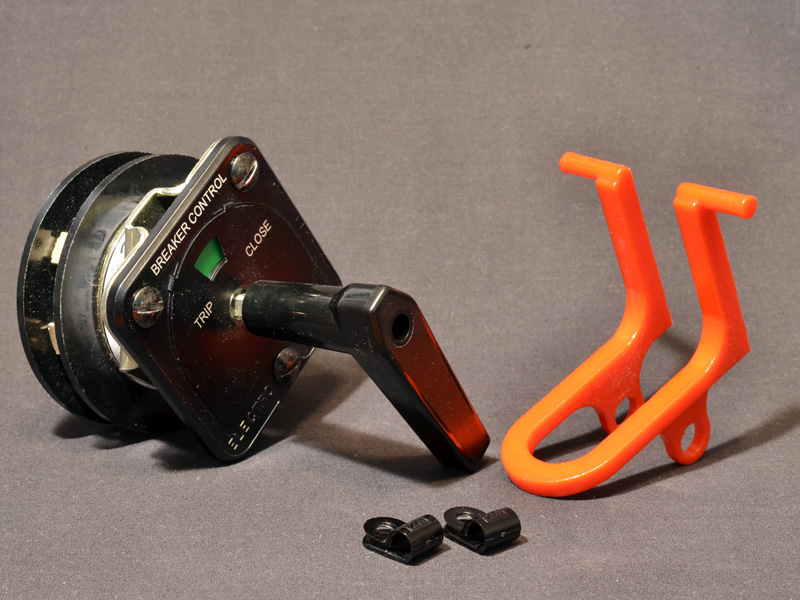
Each CS Lockout kit includes a CS Lockout Device in red plastic and two hinge clips. The kit also includes longer screws for mounting to the faceplate, which may not be needed for all control switch models (not shown). Note that the installation instructions show a loose control switch, but the CS Lockout Device is designed to be installed on a control switch that is in use and mounted.
Step 1

Remove the top two faceplate screws from the control switch.
Step 2

Attach the hinge clips to the CS Lockout Device as shown. The orientation of the hinge clips depends on the type of control switch you are installing the CS Lockout Device on (see Note 3 and Note 4 below).
Step 3

For ease of installation, start the screws on the hinge clips.
Step 4

Attach the CS Lockout Device to the front of the control switch. If the original screws are too short, use the longer screws included in the CS Lockout Device kit.
Step 5

Your CS Lockout Device is now ready to use. To lock out your control switch, use a safety lock as shown. Without the lock, the CS Lockout Device also acts as a guard to prevent accidental operation.
Note 1
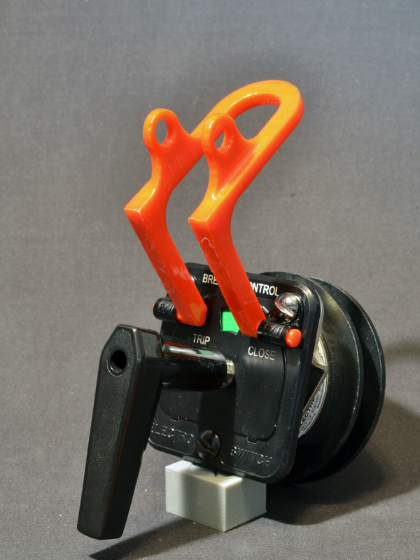
When operating the control switch, fold the CS Lockout Device up as shown.
Note 2

The CS Lockout Device can be installed on a variety of pistol-grip control switches.
Note 3

For some control switches, mount the CS Lockout Device as shown with the hinge below the faceplate screws.
Note 4
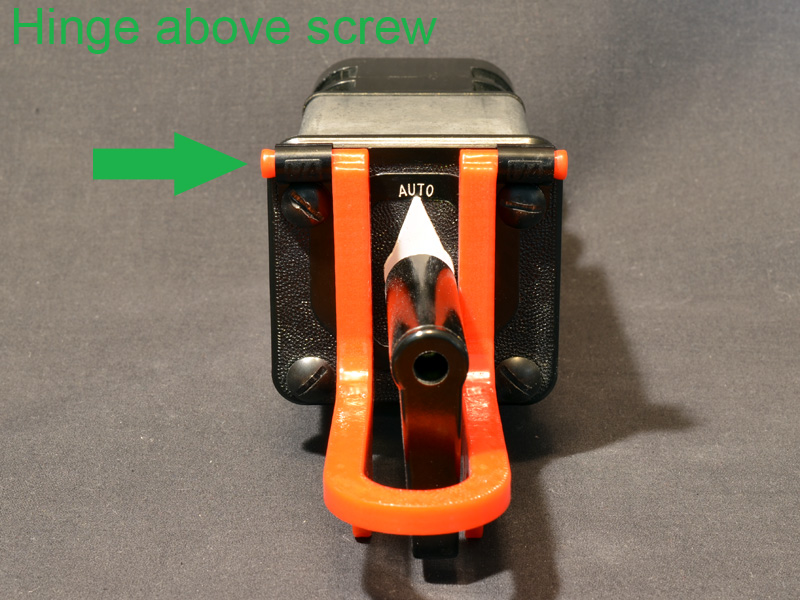
For other models of control switch, you may need to mount the CS Lockout Device with the hinge above the faceplate screws as shown to ensure proper function.
